このビデオは次のことを示しています。RaspberryPi3ボードに、GPIOコネクタを介して、HDMIモニターが接続されているMars Rover2rpi FPGAボード(Cyclone IV)が接続されています。2番目のモニターは、標準のHDMI RaspberryPi3コネクターを介して接続されます。すべてが一緒になって、2つのモニターを備えたシステムのように機能します。
これがどのように行われるかをさらに説明します。
人気のあるRaspberryPi3ボードには、さまざまな拡張ボード(センサー、LED、ステッパーモータードライバーなど)を接続できるGPIOコネクタがあります。コネクタの各ピンの特定の機能は、ポート構成によって異なります。 ALT2 GPIO構成では、コネクタをDPIインターフェイスモードであるディスプレイパラレルインターフェイスに切り替えることができます。 DPIを介してVGAモニターを接続するための拡張カードがあります。ただし、第一に、VGAモニターはHDMIほど一般的ではなくなり、第二に、デジタルインターフェースはアナログよりも優れています。さらに、同様のVGA拡張カードのDACは通常、R-2-Rチェーンの形式で作成され、多くの場合、色あたり6ビット以下です。
ALT2モードでは、GPIOピンの意味は次のとおりです。
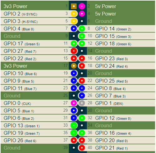
ここでは、コネクタのRGBピンをそれぞれ赤、緑、青で色付けしました。その他の重要な信号は、V-SYNCおよびH-SYNCスイープ同期信号とCLKです。 CLKクロックは、ピクセル値がコネクタに出力される周波数であり、選択したビデオモードによって異なります。
デジタルHDMIモニターを接続するには、DPI信号をキャプチャしてHDMI信号に変換する必要があります。これは、たとえば、ある種のFPGAボードを使用して実行できます。結局のところ、Marsrover2rpiボードはこれらの目的に適しています。実際、このボードを特別なアダプターを介して接続するための主なオプションは次のようになります。
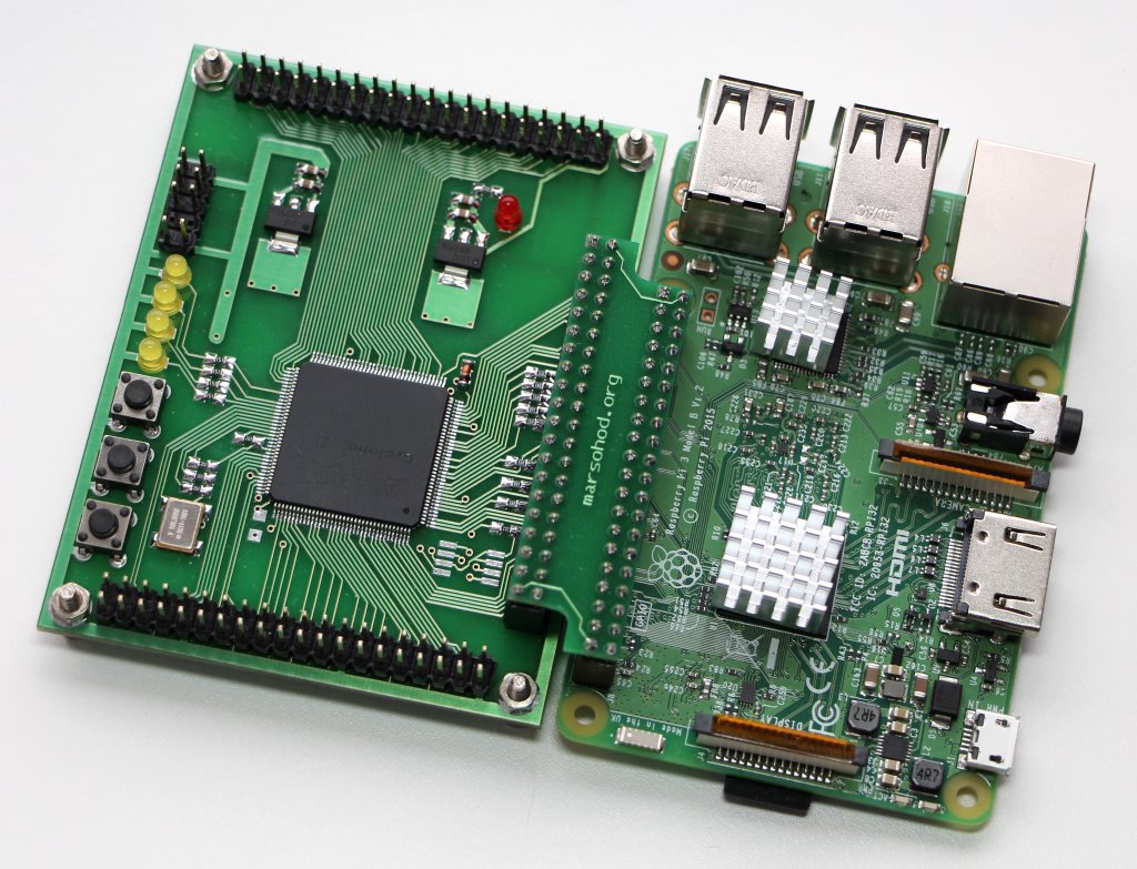
このボードは、GPIOポートの数を増やし、より多くの周辺機器をラズベリーに接続するのに役立ちます。同時に、この接続で4つのGPIO信号がJTAG信号に使用されるため、ラズベリーからのプログラムはFPGAファームウェアをFPGAにロードできます。このため、このような標準接続は私には適さず、4つのDPI信号がドロップアウトします。幸い、ボード上の追加のコームには、ラズベリー互換のピン配置があります。ボードを90度回転させても、ラズベリーに接続できるようにします。

もちろん、外部のJTAGプログラマーを使用する必要がありますが、それは問題ではありません。
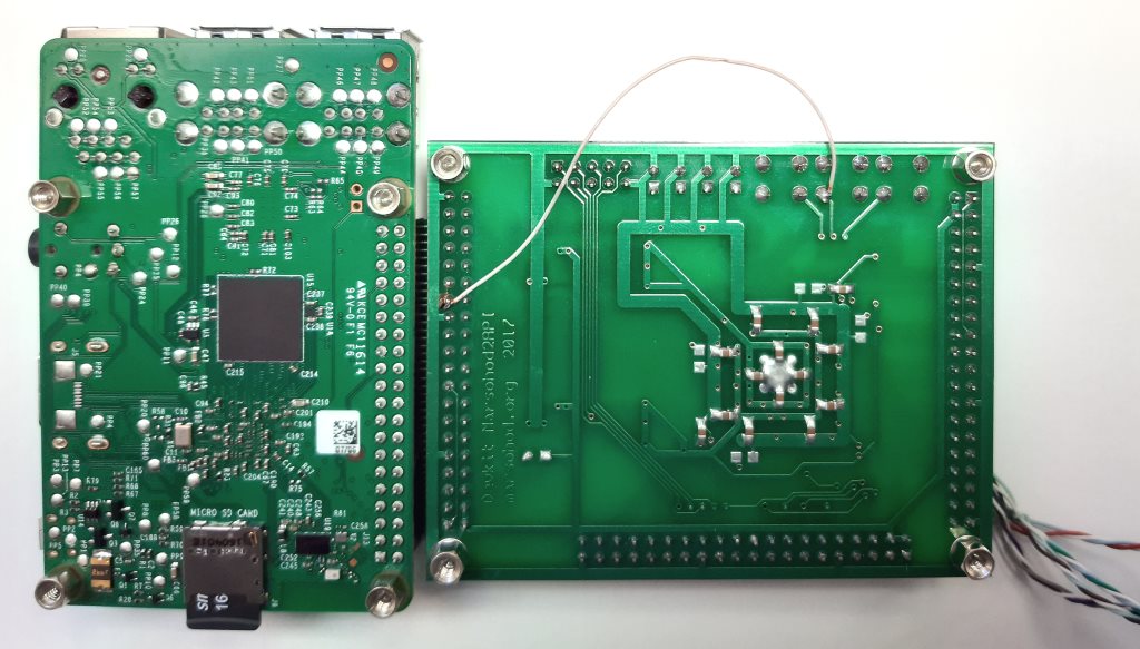
まだ小さな問題があります。すべてのFPGAピンをクロック入力として使用できるわけではありません。この目的に使用できる専用ピンはごくわずかです。したがって、ここで、GPIO_0 CLK信号はFPGA入力に送られず、FPGAクロック周波数入力として使用できることがわかりました。それで、私はスカーフに1本のワイヤーを投げなければなりませんでした。 GPIO_0とボードのKEY [1]信号を接続し
ます。次に、FPGAのプロジェクトについて少し説明します。 HDMI信号を形成する際の主な問題は、非常に高い周波数です。 HDMIコネクタのピン配列を見ると、RGB信号がシリアル差動信号になっていることがわかります。

差動信号を使用すると、伝送ラインのコモンモードノイズと戦うことができます。したがって、各カラー信号の元の8ビットコードは10ビットTMDS(遷移最小化差動信号)に変換されます。これは、信号からDC成分を除去し、差動ラインでの信号スイッチングを最小限に抑えるための特別なコーディング手法です。 1バイトのカラーはシリアル伝送ラインを介して10ビットを送信する必要があるため、シリアライザーのクロック周波数はピクセルのクロック周波数の10倍である必要があります。たとえば、ビデオモード1280x720 60Hzを使用すると、このモードのピクセル周波数は74.25MHzになります。シリアライザーは742.5MHzである必要があります。
残念ながら、従来のFPGAではこれができません。ただし、幸いなことに、FPGAにはDDIOピンが組み込まれています。これらは、すでに一種の2対1のシリアライザーである結論です。つまり、クロック周波数の立ち上がりエッジと立ち下がりエッジで2つの連続したビットを出力できます。つまり、FPGAプロジェクトでは、740MHzではなく370MHzを使用できますが、FPGAでDDIO出力要素を使用する必要があります。ここでは、370MHzはすでにかなり達成可能な周波数です。残念ながら、1280x720モードが限界です。 Mars Rover2rpiボードにインストールされたFPGACycloneIVではより高い解像度を実現できません。
したがって、プロジェクトでは、入力ピクセル周波数CLKがPLLに送られ、そこで5が乗算されます。この周波数で、バイトR、G、Bがビットのペアに変換されます。これはTMDSエンコーダーによって行われます。 VerilogHDLのソースコードは次のようになります。
module hdmi(
	input wire pixclk,		// 74MHz
	input wire clk_TMDS2,	// 370MHz
	input wire hsync,
	input wire vsync,
	input wire active,
	input wire [7:0]red,
	input wire [7:0]green,
	input wire [7:0]blue,
	output wire TMDS_bh,
	output wire TMDS_bl,
	output wire TMDS_gh,
	output wire TMDS_gl,
	output wire TMDS_rh,
	output wire TMDS_rl
);

wire [9:0] TMDS_red, TMDS_green, TMDS_blue;
TMDS_encoder encode_R(.clk(pixclk), .VD(red  ), .CD({vsync,hsync}), .VDE(active), .TMDS(TMDS_red));
TMDS_encoder encode_G(.clk(pixclk), .VD(green), .CD({vsync,hsync}), .VDE(active), .TMDS(TMDS_green));
TMDS_encoder encode_B(.clk(pixclk), .VD(blue ), .CD({vsync,hsync}), .VDE(active), .TMDS(TMDS_blue));

reg [2:0] TMDS_mod5=0;  // modulus 5 counter
reg [4:0] TMDS_shift_bh=0, TMDS_shift_bl=0;
reg [4:0] TMDS_shift_gh=0, TMDS_shift_gl=0;
reg [4:0] TMDS_shift_rh=0, TMDS_shift_rl=0;

wire [4:0] TMDS_blue_l  = {TMDS_blue[9],TMDS_blue[7],TMDS_blue[5],TMDS_blue[3],TMDS_blue[1]};
wire [4:0] TMDS_blue_h  = {TMDS_blue[8],TMDS_blue[6],TMDS_blue[4],TMDS_blue[2],TMDS_blue[0]};
wire [4:0] TMDS_green_l = {TMDS_green[9],TMDS_green[7],TMDS_green[5],TMDS_green[3],TMDS_green[1]};
wire [4:0] TMDS_green_h = {TMDS_green[8],TMDS_green[6],TMDS_green[4],TMDS_green[2],TMDS_green[0]};
wire [4:0] TMDS_red_l   = {TMDS_red[9],TMDS_red[7],TMDS_red[5],TMDS_red[3],TMDS_red[1]};
wire [4:0] TMDS_red_h   = {TMDS_red[8],TMDS_red[6],TMDS_red[4],TMDS_red[2],TMDS_red[0]};

always @(posedge clk_TMDS2)
begin
	TMDS_shift_bh <= TMDS_mod5[2] ? TMDS_blue_h  : TMDS_shift_bh  [4:1];
	TMDS_shift_bl <= TMDS_mod5[2] ? TMDS_blue_l  : TMDS_shift_bl  [4:1];
	TMDS_shift_gh <= TMDS_mod5[2] ? TMDS_green_h : TMDS_shift_gh  [4:1];
	TMDS_shift_gl <= TMDS_mod5[2] ? TMDS_green_l : TMDS_shift_gl  [4:1];
	TMDS_shift_rh <= TMDS_mod5[2] ? TMDS_red_h   : TMDS_shift_rh  [4:1];
	TMDS_shift_rl <= TMDS_mod5[2] ? TMDS_red_l   : TMDS_shift_rl  [4:1];
	TMDS_mod5 <= (TMDS_mod5[2]) ? 3'd0 : TMDS_mod5+3'd1;
end

assign TMDS_bh = TMDS_shift_bh[0];
assign TMDS_bl = TMDS_shift_bl[0];
assign TMDS_gh = TMDS_shift_gh[0];
assign TMDS_gl = TMDS_shift_gl[0];
assign TMDS_rh = TMDS_shift_rh[0];
assign TMDS_rl = TMDS_shift_rl[0];

endmodule

module TMDS_encoder(
	input clk,
	input [7:0] VD,	// video data (red, green or blue)
	input [1:0] CD,	// control data
	input VDE,  	// video data enable, to choose between CD (when VDE=0) and VD (when VDE=1)
	output reg [9:0] TMDS = 0
);

wire [3:0] Nb1s = VD[0] + VD[1] + VD[2] + VD[3] + VD[4] + VD[5] + VD[6] + VD[7];
wire XNOR = (Nb1s>4'd4) || (Nb1s==4'd4 && VD[0]==1'b0);
wire [8:0] q_m = {~XNOR, q_m[6:0] ^ VD[7:1] ^ {7{XNOR}}, VD[0]};

reg [3:0] balance_acc = 0;
wire [3:0] balance = q_m[0] + q_m[1] + q_m[2] + q_m[3] + q_m[4] + q_m[5] + q_m[6] + q_m[7] - 4'd4;
wire balance_sign_eq = (balance[3] == balance_acc[3]);
wire invert_q_m = (balance==0 || balance_acc==0) ? ~q_m[8] : balance_sign_eq;
wire [3:0] balance_acc_inc = balance - ({q_m[8] ^ ~balance_sign_eq} & ~(balance==0 || balance_acc==0));
wire [3:0] balance_acc_new = invert_q_m ? balance_acc-balance_acc_inc : balance_acc+balance_acc_inc;
wire [9:0] TMDS_data = {invert_q_m, q_m[8], q_m[7:0] ^ {8{invert_q_m}}};
wire [9:0] TMDS_code = CD[1] ? (CD[0] ? 10'b1010101011 : 10'b0101010100) : (CD[0] ? 10'b0010101011 : 10'b1101010100);

always @(posedge clk) TMDS <= VDE ? TMDS_data : TMDS_code;
always @(posedge clk) balance_acc <= VDE ? balance_acc_new : 4'h0;

endmodule
次に、出力ペアがDDIO出力に供給され、DDIO出力は立ち上がりと立ち下がりで1ビット信号を順次生成します。
DDIO自体は、次のようなVerilogコードで記述できます。
module ddio(
	input wire d0,
	input wire d1,
	input wire clk,
	output wire out
	);

reg r_d0;
reg r_d1;
always @(posedge clk)
begin
	r_d0 <= d0;
	r_d1 <= d1;
end
assign out = clk ? r_d0 : r_d1;
endmodule
しかし、おそらくそのようには機能しません。実際に出力DDIO要素を使用するには、altermegafunctionALTDDIO_OUTを使用する必要があります。私のプロジェクトで使用されているのはALTDDIO_OUTライブラリコンポーネントです。
それはすべて少しトリッキーに見えるかもしれませんが、それは機能します。
Verilog HDLで記述されたすべてのソースコードは、ここgithubで表示できます。
コンパイルされたFPGAファームウェアは、MarsRover2rpiボードにインストールされたEPCSチップに組み込まれます。したがって、FPGAボードに電力が供給されると、FPGAはフラッシュメモリから初期化されて起動します。
次に、Raspberry自体の構成について少し説明する必要があります。
私はDebianBuster、バージョン:2020年8月に基づくRaspberry PI OS(32ビット)で実験を行っています。
リリース日:2020-08-20、カーネルバージョン:5.4。
行うべき2つのことがあります:
- config.txtファイルを編集します。
- 2つのモニターで動作するXサーバー構成を作成します。
/boot/config.txtファイルを編集するときは、次のことを行う必要があります。
- i2c、i2s、spiの使用を無効にします。
- オーバーレイを使用してDPIモードを有効にしますdtoverlay = dpi24;
- ビデオモードを1280x72060Hzに設定し、DPIごとにポイントごとに24ビット。
- 必要なフレームバッファ数2を指定します(max_framebuffers = 2の場合のみ、2番目のデバイス/ dev / fb1が表示されます)
config.txtファイルの全文は次のようになります。
# For more options and information see
# http://rpf.io/configtxt
# Some settings may impact device functionality. See link above for details

# uncomment if you get no picture on HDMI for a default "safe" mode
#hdmi_safe=1

# uncomment this if your display has a black border of unused pixels visible
# and your display can output without overscan
disable_overscan=1

# uncomment the following to adjust overscan. Use positive numbers if console
# goes off screen, and negative if there is too much border
#overscan_left=16
#overscan_right=16
#overscan_top=16
#overscan_bottom=16

# uncomment to force a console size. By default it will be display's size minus
# overscan.
#framebuffer_width=1280
#framebuffer_height=720

# uncomment if hdmi display is not detected and composite is being output
hdmi_force_hotplug=1

# uncomment to force a specific HDMI mode (this will force VGA)
#hdmi_group=1
#hdmi_mode=1

# uncomment to force a HDMI mode rather than DVI. This can make audio work in
# DMT (computer monitor) modes
#hdmi_drive=2

# uncomment to increase signal to HDMI, if you have interference, blanking, or
# no display
#config_hdmi_boost=4

# uncomment for composite PAL
#sdtv_mode=2

#uncomment to overclock the arm. 700 MHz is the default.
#arm_freq=800

# Uncomment some or all of these to enable the optional hardware interfaces
#dtparam=i2c_arm=on
#dtparam=i2s=on
#dtparam=spi=on

dtparam=i2c_arm=off
dtparam=spi=off
dtparam=i2s=off

dtoverlay=dpi24
overscan_left=0
overscan_right=0
overscan_top=0
overscan_bottom=0
framebuffer_width=1280
framebuffer_height=720
display_default_lcd=0
enable_dpi_lcd=1
dpi_group=2
dpi_mode=87
#dpi_group=1
#dpi_mode=4
dpi_output_format=0x6f027
dpi_timings=1280 1 110 40 220 720 1 5 5 20 0 0 0 60 0 74000000 3

# Uncomment this to enable infrared communication.
#dtoverlay=gpio-ir,gpio_pin=17
#dtoverlay=gpio-ir-tx,gpio_pin=18

# Additional overlays and parameters are documented /boot/overlays/README

# Enable audio (loads snd_bcm2835)
dtparam=audio=on

[pi4]
# Enable DRM VC4 V3D driver on top of the dispmanx display stack
#dtoverlay=vc4-fkms-v3d
max_framebuffers=2

[all]
#dtoverlay=vc4-fkms-v3d
max_framebuffers=2
その後、Xサーバーが2つのフレームバッファー/ dev / fb0および/ dev / fb1で2つのモニターを使用するための構成ファイルを作成する必要があります:
私の設定ファイル/usr/share/x11/xorg.conf.d/60-dualscreen.confは次のようになります
Section "Device"
        Identifier      "LCD"
        Driver          "fbturbo"
        Option          "fbdev" "/dev/fb0"
        Option          "ShadowFB" "off"
        Option          "SwapbuffersWait" "true"
EndSection

Section "Device"
        Identifier      "HDMI"
        Driver          "fbturbo"
        Option          "fbdev" "/dev/fb1"
        Option          "ShadowFB" "off"
        Option          "SwapbuffersWait" "true"
EndSection

Section "Monitor"
        Identifier      "LCD-monitor"
        Option          "Primary" "true"
EndSection

Section "Monitor"
        Identifier      "HDMI-monitor"
        Option          "RightOf" "LCD-monitor"
EndSection

Section "Screen"
        Identifier      "screen0"
        Device          "LCD"
        Monitor         "LCD-monitor"
EndSection

Section "Screen"
        Identifier      "screen1"
        Device          "HDMI"
	Monitor         "HDMI-monitor"
EndSection

Section "ServerLayout"
        Identifier      "default"
        Option          "Xinerama" "on"
        Option          "Clone" "off"
        Screen 0        "screen0"
        Screen 1        "screen1" RightOf "screen0"
EndSection
まだインストールされていない場合は、Xineramaをインストールする必要があります。次に、上記のデモビデオに示すように、デスクトップスペースが2つのモニターに完全に拡張されます。
おそらくそれだけです。これで、RaspberryPi3の所有者は2つのモニターを使用できるようになります。
火星のrover2rpiボードの説明と図はここで見ることができます。